3-D Modeling Using Gocad
Gocad stands for “Geologic Computer Aided Design.” It is a program specifically written for the oil and gas industry so it has many data types that are tailored for geologic use. Although petroleum geoscientists generally use it to construct 3-D models based on subsurface data, it can be used with surface data to extend to the subsurface. “3-D Modeling” in this context refers specifically to the geometric construction of structures, or earth modeling, and not the more general way we might use modeling in geology.
Use the 2009 version of Gocad for this primer (note this version is similar to earlier versions, like 2.08, but this version requires an overall project shell and some menus are in different places).
Getting Help
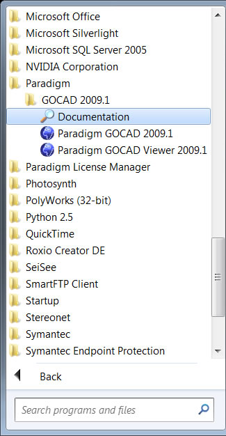
The help files are elaborate, but quite serviceable. Note, for some reason, when you access help from the Help Menu within Gocad it gives a Java error, so use the help from the Windows Start Meun -> Paradigm -> Documentation, or you should be able to use help buttons within dialog boxes.
Starting Gocad
Gocad is a licensed product. Normally this should be transparent to you, but we are having problems with the license server right now. If you get an error message asking for a license file, navigate to Q:\Courses\Geo 335-Petroleum\Gocad_primers\Washington and Lee University_005056b222ce_1_18_2012.lic.
We have only four licenses for Gocad, so only four of you can work concurrently. When you are not using the program, please quit the program so that a license frees up for another student.
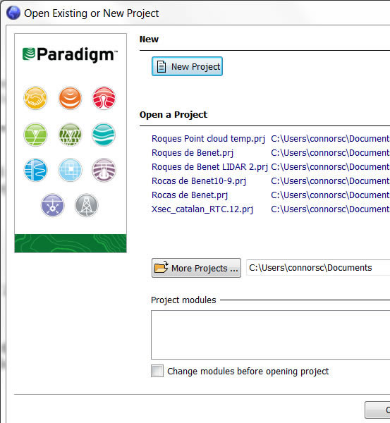
When starting Gocad 2009 and later versions, you need to have an overall project shell with a .gprj extension. So once you have a functioning Gocad (license has been selected above), it will prompt you to open an existing project or create a new one. For your first tutorial, give it a name, such as "gocad_tutorial_1_my-intials", in YOUR DIRECTORY (not the class directory).
Gocad is actually a software environment with many modules (tools to do different things). It will prompt you in the Project Module dialog for which modules you want to load. Just click "Select All".
The units need to be determined. In this case the data is elevation data so use the following:
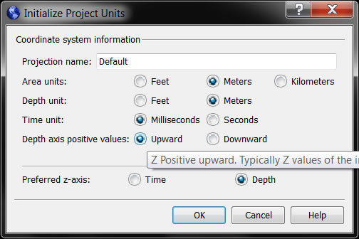
Note this will NOT always be what you use for your own projects. This should be guided by your data.
Importing X Y Z Data
Import the point data (locations with elevations at spot locations, such as would be in data of formation tops from wells). Chooose File Menu>Import Objects>Horizon Interpretation>PointSet>X Y Z as a PointSet
(Note a completed version of this project is called dmap.gprj in the Q:\Courses\Geol 335-Petroleum\Gocad_primers. You can copy this to your private directory to see the final result and compare to yours.)
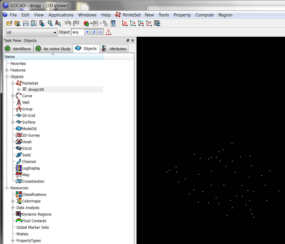
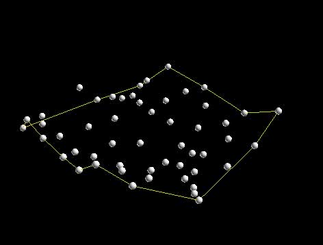
After selecting the file “dmap100.txt” and saying OK you should see a new PointSet appear under the list of variables in the Objects Tab:
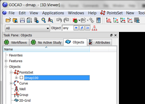
Turn it on by clicking the check box and you will see the point data in the camera window. You can change the way the points are seen by clicking the attributes tab, or the icons at the bottom of the window.
Making a Direct Surface from the Points
In Gocad there are many ways to make a surface with point data, we will show just two ways here. For direct Delaunay of the points such as one does in Matlab choose the menu General>Surface
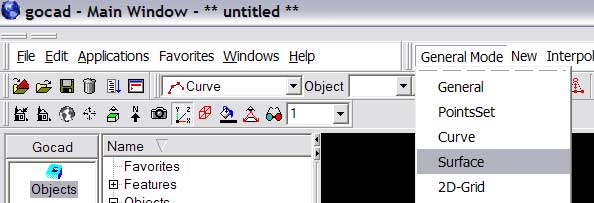
Note this changes all of the other menus to the right making them specific to surfaces. Then choose the menu New>From PointSet
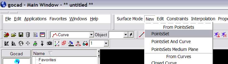
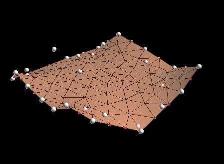
After you name the new surface (we chose “dmap_direct_suf”) you will see a surface built of triangles where every point is the vertex of a triangle
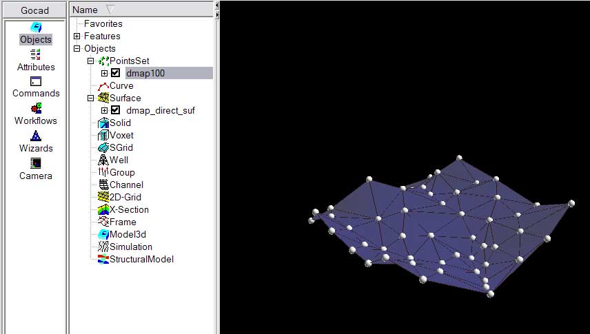
This is sometimes satisfactory, such as with topography that has a number of data points, but there are times when irregularly spaced data may require you to do something more. In Matlab, and most other programs, we grid the data, in Gocad we will first build a surface and then fit the surface to the known points.
Making a Surface by Fitting The Surface to the Points
1. Make a convex hull of the object by choosing the Curve Menu then choosing New>Convex Hull>Of Object (NOTE: we had to change menus again, this time to Curve Mode)
2. Densify the hull to make the sampling along the line consistent. Tools>Densify and use 100 as the density
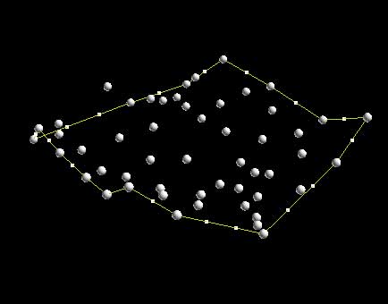
3. Make a new surface from the hull. Choose Surface Menu then New>From Closed Curve. After you name the new surface and say OK your cursor will turn into a cross hair and you are to click the hull in the window that you wan to make of surface of. If you have done this right you should see the following:
4. Set the constraints. The fitting of surface is Gocad’s bread and butter and it is involved, but you basically need to understand that Control Nodes fix parts of a surface so that it won’t move and Constraints guide the fitting of the surface by fitting to these points. First, get ride of the control nodes, but choosing Constraints>Control Nodes>Unset Everywhere. Next make the border of the surface not change in aerial extent by choosing Constraints> Constraints on Border>Set on Cylinder, One Border. Note you will get a cross-hair cursor again so you will need to click the border of the surface. Finally set the constraints to fit the surface with the known data by choosing Constraints> Control Points>Set Control Points. If done right you should see the following:
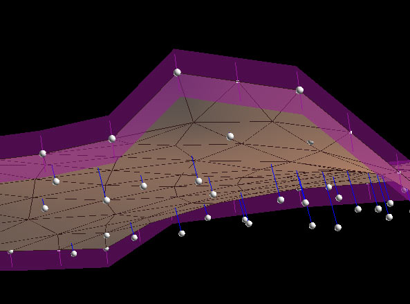
I have rotated the surface to show the blue lines connecting the points to the surface. These show the constraints that you have placed. That is when we interpolate the surface the surface will warp to fit to these points.
5. Fit the Surface. Choose Interpolate>On Entire Surface and you should
see a warped surface: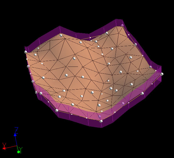
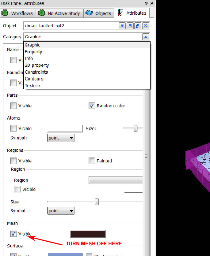
6. Clean Up and make pretty. Turn off everything but the surface. Then click the Attibutes Tab. This brings up a different window for the center panel which has a menu at the top which changes the choices below (yes this is really involved). I have shown just one choice here (turning off the mesh):
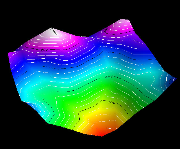
Continue by turning off the viewing of all constraints, turn off the mesh, add contours and add color properties of Z. Note you will need to choose different menus to do this. Once done you should have a completed surface that looks like this:
to learn more about using Gocad, try the advance primer
Connors, revised '12