3-D Modeling Using Gocad
Gocad stands for “Geologic Computer Aided Design.” It is a program specifically written for the oil and gas industry so it has many data types tailored for geologic use. Although petroleum geoscientists generally use it to construct 3-D models based on subsurface data, it can be used with surface data to extend to the subsurface. “3-D Modeling” or “Earth Modeling” in this context refers specifically to the geometric construction of structures and not the more general way we often use it in geology. The current version of Gocad is bundled in a broader package called SKUA-GOCAD 19 on our machines. NOTE This tutorial was originally based on an older version of Gocad, and I have tried to update it but you might have to look around different menus/panels at certain points.
Getting Help
As always I admonish you to use the help system which although not as good as Matlab’s is quite serviceable. You can access help from the Help Menu.
Start by creating a new project. Use Meters and Depth Axis positive values upward.
Note projects in Gocad are directories with lots of files in them. Do not muck around in these. Always create, open, save, etc within Gocad.
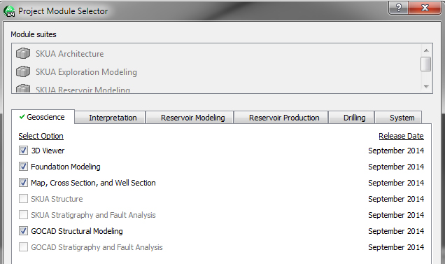
Turn on all the check boxes that you can in the Geoscience and Interpretaton tabs. These should be preselected for you and you can just leave them checked.
Importing X Y Z Data
Chooose File Menu>Import >Horizon Interpretaton>X Y Z File as a PointSet
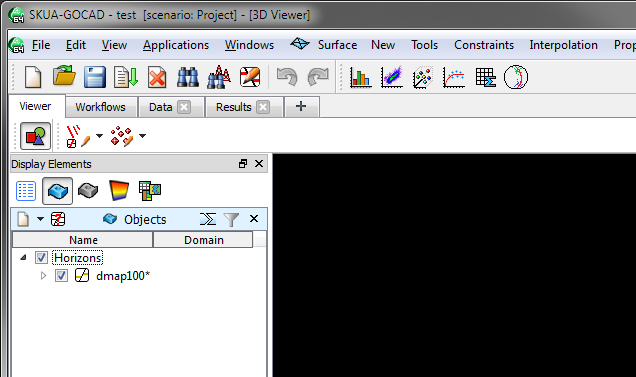
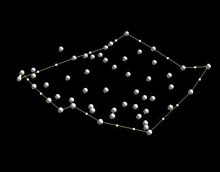
Navigate to "R:\courses\Geo 335-Petroleum 2022". After selecting the file “dmap100.txt” and saying OK you should see a new PointSet appear under the list of variables:
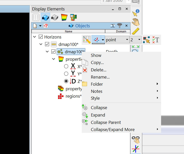
Turn it on by clicking the check box and you will see the point data in the camera window. Change some of the properties such as the point shape and the color values for Z.
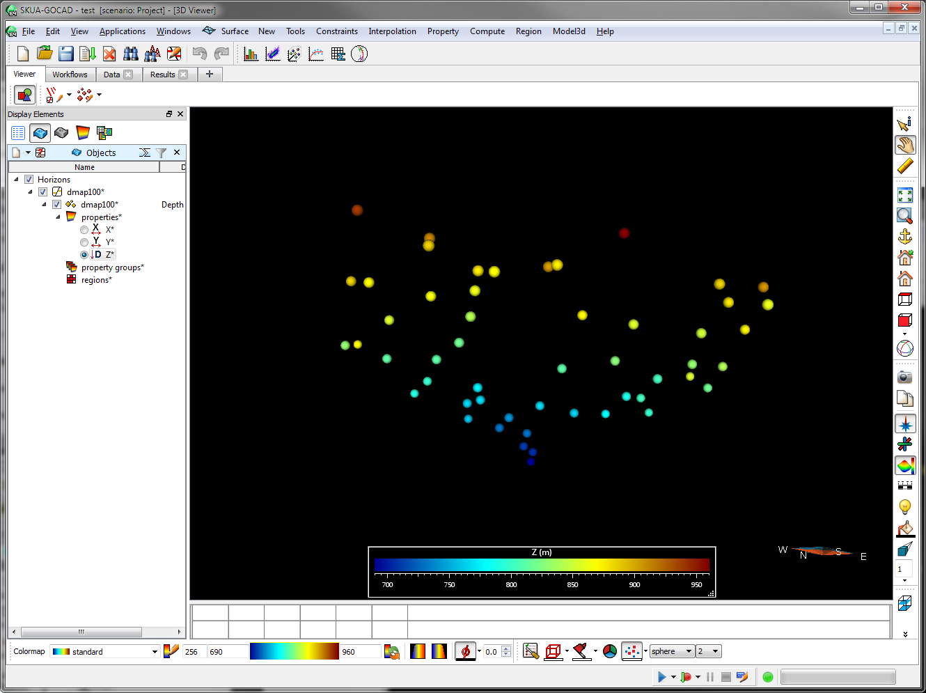
Do this by right-clicking the object. Many of the choices are at the top of the popup, or you can choose the left-most icon to get a whole palette of choices. Play with this. It is one of the great things about Gocad, and something you will want to use when your datasets get complicated.
Making a Direct Surface from the Points
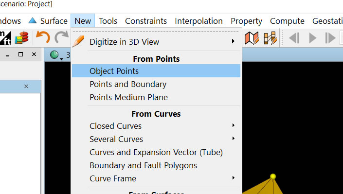
In Gocad there are many ways to make a surface with point data, we will show just two ways here. For direct Delaunay of the points such as we did in Matlab choose the menu General (rightmost menu, it might say "Hide Comands" when you start the prgram), and change it to Surface Mode. Note this changes all of the other menus to the right making them specific to surfaces. Then choose the menu New>From Points. NOTE there is more than one way to do this because the menus are context sensitive and change! I told you it was an involved program. Do not just make the selection and then stop. Try different menus notice how they change. That is, on your own learn how the interface is constructed. If you are working in a team, each of you play with this.
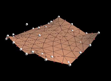
After you name the new surface (we chose “dmap_direct_suf”) you will see a surface built of triangles where every point is the vertex of a triangle
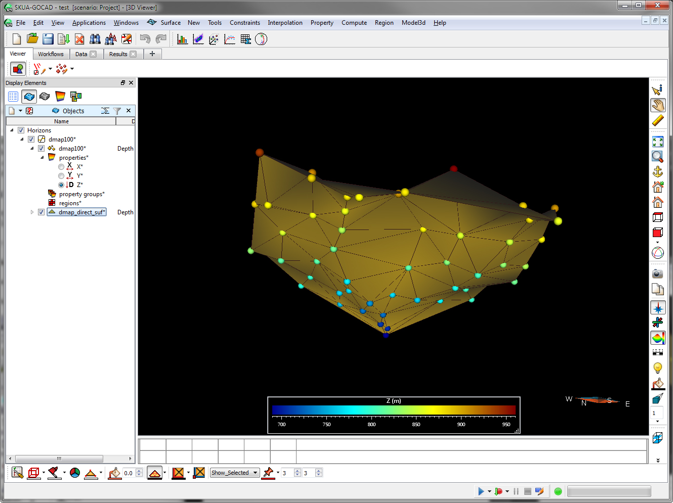
This is sometimes satisfactory, such as with topography that has a number of data points, but just as we talked about with making surfaces in Matlab, there are times when irregularly spaced data may require you to do something more. In Matlab we grided the data, in Gocad we will first build a surface and then fit the surface to the known points.
Making a Surface by Fitting The Surface to the Points
1. Make a convex hull of the object by choosing the Curve Menu then choosing New>Convex Hull>Of Object (NOTE: we had to change menus again, this time to Curve Mode)
2. Densify the hull to make the sampling along the line consistent. From Curves Menu Tools >Densify and use 100 as the density. If you are not seeing the points on the hull make sure to display those for the object (right click...).
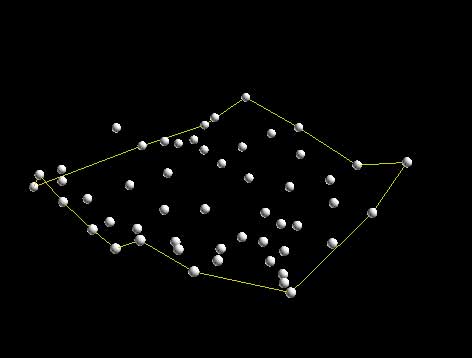
3. Make a new surface from the hull. Choose Surface Menu then New>From Closed Curve (in this case a Single Curve). After you name the new surface and say OK your cursor will turn into a cross hair and you are to click the hull in the window that you wan to make of surface of. If you have done this right you should see the following:
4. Set the constraints. The fitting of a surface is Gocad’s bread and butter and it is involved, but you basically need to understand that Control Nodes fix parts of a surface so that it won’t move and Constraints guide the fitting of the surface by fitting to these points. Control Nodes are displayed as little cubes, and Constraints as "rubberband-like" lines. Slow down, look for these as you are modeling. Right click the object and leave the palette open so you can see what is visible and what is not visable.
First, get ride of the control nodes, by choosing Constraints>Control Nodes>Unset Everywhere.
Next make the border of the surface not change in aerial extent by choosing Constraints> Constraints on Border>Set on Cylinder, One Border. Note you will get a cross-hair cursor again so you will need to click the border of the surface.
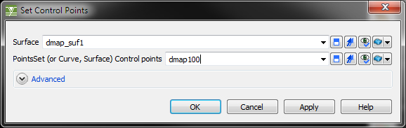
Finally set the constraints to fit the surface with the known data by choosing Constraints> Control Points>Set Control Points.
Be mindful that you only are setting the constraint of the points NOT of the surface on itself. THIS IS THE NUMBER ONE BIGGEST MISTAKE STUDENTS MAKE. They do not pay attention to the dialog boxes and just click OK. Slow down and always check that you are doing what you want.
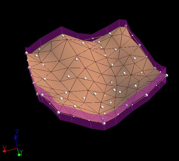
If done right it should like something like this:
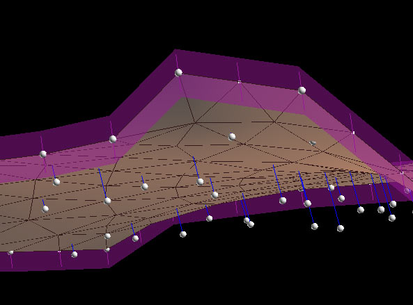
I have rotated the surface to show the blue lines connecting the points to the surface. These show the constraints that you have placed. That is when we interpolate the surface the surface will warp to fit to these points.
5. Fit the Surface. Choose Interpolate>On Entire Surface and you should see a warped surface:
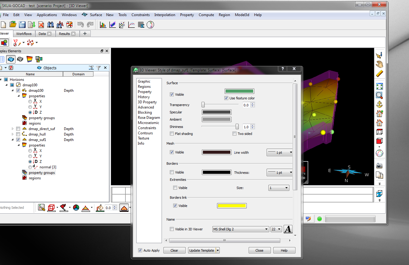
6. Clean Up and make pretty. Do this by going to the attributes of the surface (right-click on surface if you don't have the palette up). Play with it. Try to figure out transparency of a property
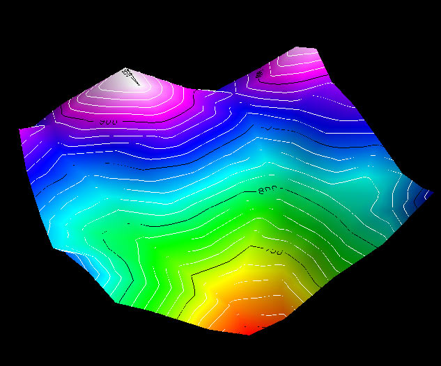
Continue by turning off the viewing of all constraints, turn off the mesh, add contours and add color properties of Z. Note you will need to choose different menus to do this. Once done you should have a completed surface that looks like this: Your first 3D model in Gocad!
C. Connors