Faulted Models in Gocad
We have seen how to make faults in Gocad using fault traces in the last primer. In this primer we are going to make faults using ribs or contours of faults.
The other main object of this primer is to learn to use control nodes to fix certain positions so they will not be altered during continued interpolation.
Open the project R:\courses\Geo 335-Petroleum 2022\faulted_model.sprj. You should immediately save the project into your Q or P drive folder. You will not be able to save the project into the R drive as it is read only. Furthermore, no other student will likely be able to use the project while you have the original one on R open. So save it now to your own directory.
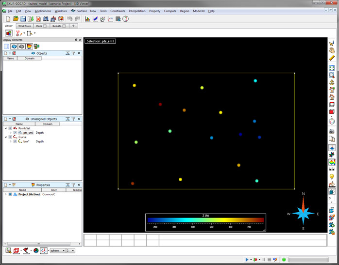
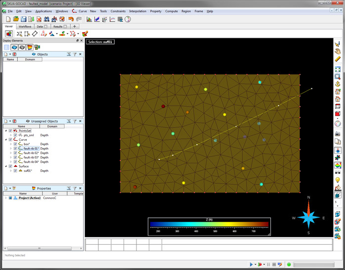
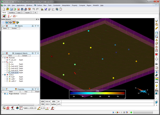
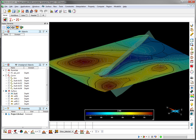
Show the Top View, and you should see colored spheres. These display the points with colors for Z values, and in their true X,Y,Z space.
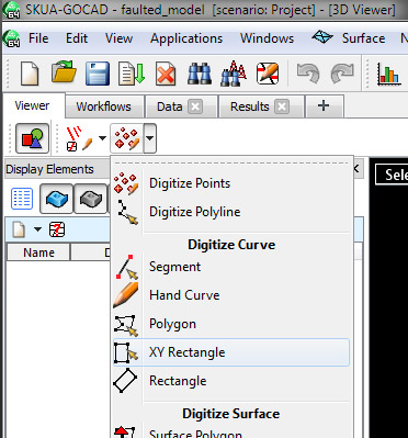
1. Create a new box that covers all the points by XY Rectangle and then drawing a box around the points.
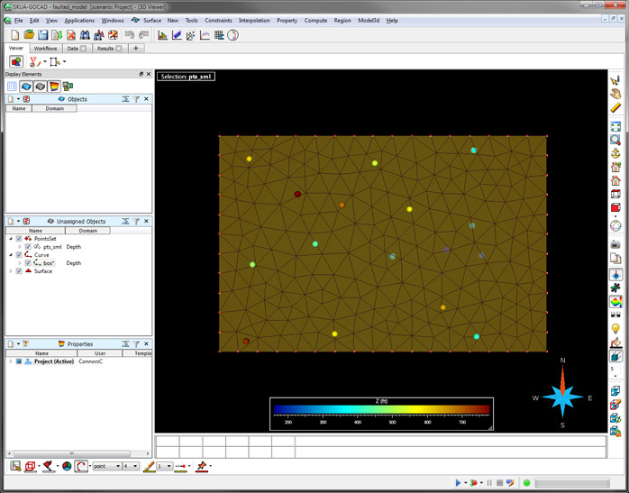
2. Densify the box to 2500 ft and make a new surface from closed curve. If you don't remember how to do these steps, refer back to earlier primers on Gocad.
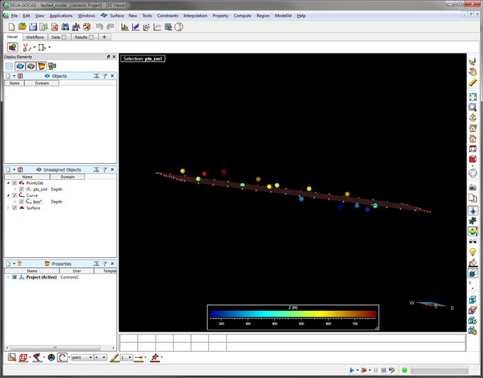
3. Now rotate the model to see that the default surface (based on the box) is the at the mean elevation of the points that were displayed when the box was made. Note also that some points are above and some are below.
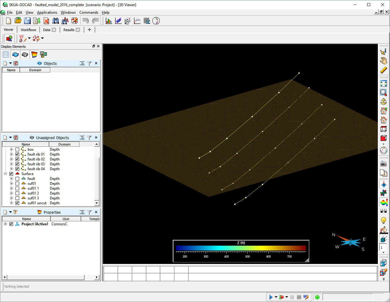
4. We are going add fault ribs (contours of the fault we are going to build) at positions that separate these regions of points above from those below. So digitize a polyline (from the same menu as in step 1) on the surface. Then make 3 duplicates of this fault rib.
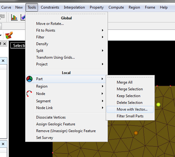
5. Now displace each of them approximately perpendicular to the fault rib (strike), some to the NW some to the SE. Do this by choosing from the Curve menu -> Tools -> Part -> Move with Vector...
Keep the change in Z = 0 at first, then move the Z and keep the change in X and Y at 0. Similar to the way you edited fault traces in the last tutorial.
Note, if you wanted to make a fault of a given dip then you would use simple trig to determine how much to displace these fault ribs.
6. Build a fault from these ribs using the Surface Menu, then Tools-> From Several Curves (like you did before for fault traces).
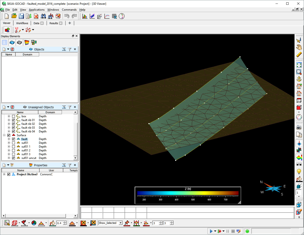
7. Now set Constraint on Border on a Cylinder for your surface, again like the previous tutorial. Then cut the surface with the fault. If done right you should see a boarder for the fault cut as a green line. Make a copy of the cut surface and then save your project.
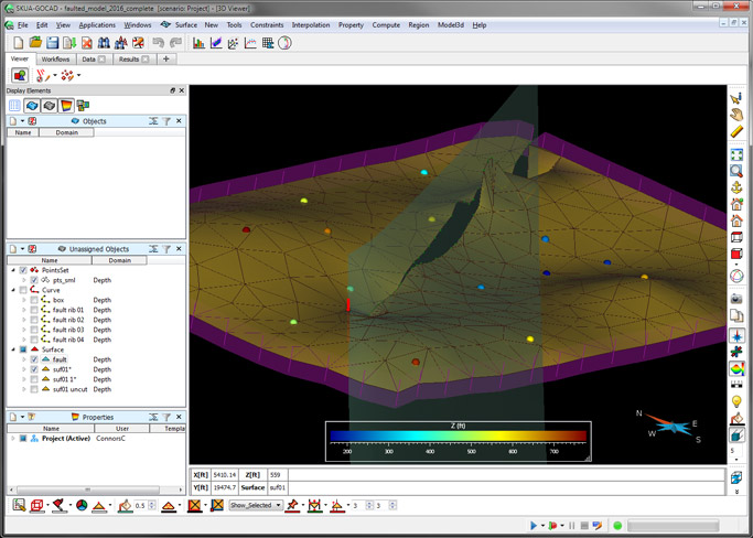
8. Set constraints with the points on the surface and run DSI (Interpolate Surface). Note, it makes a water-tight (good) but unrealistic, wavy (bad) suface.
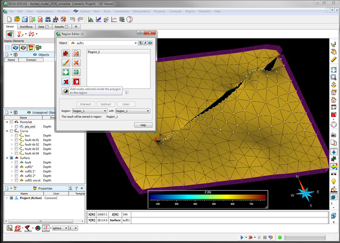
9. So we need to fix that bad part of the surface as discussed below, but first you need define that part. In this case the footwall on the right side. Do this by making a Region from the Surface Menu then Region -> Region Editor... Paint the nodes in FW that you like as "Region 1." The new Region 1 has nodes that are white in the figure below.
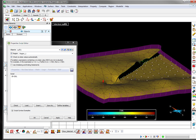
10. Next force this region to be a defined value using the Surface Menu, then Compute -> On Object, then click the Region check box. Apply the script as defined Z=200;
11. Then run DSI again to smooth it all out. Then clean up: hide the mesh, hide the nodes, show contours, property, etc. Note, even this isn't perfect. One could tweek the edge of the surface in the HW in the upper right for example. To do this you could use from the Surface Menu the Tools -> Node -> Move by Dragging... Then you would run DSI (interpolation) again to bring it back to smooth. The key to all this is to tweek things, and narrow in on the suface you like. Another thing to make use of is Control Nodes defined by Regions. Try that and see what happens.
C. Connors