More Gocad
Open the dmap project from your earlier Gocad primer. You might want to save it as a new project so you have both, or just make sure you don't blow away the old surfaces. In the past primer we modeled it as a continuous surface, such as topography, but what if we thought this were data of a bed that was faulted? How could we incorporate the fault?
Let’s say there is a fault through the center of the data east-west that offsets the northern data above (higher Y) from the southern data as a normal fault. Our approach will be to create a fault and then cut an uninterpolated surface with the fault and then interpolate each surface (fault block) separately.
With this primer we will get just a taste of how flexible Gocad is for shaping surfaces by modeling a faulted surface. Traditionally one would contour by hand each fault block separately bound by a line that represented the fault through that bed. We will sort of do this, but in 3-D with the fault as an actual surface.
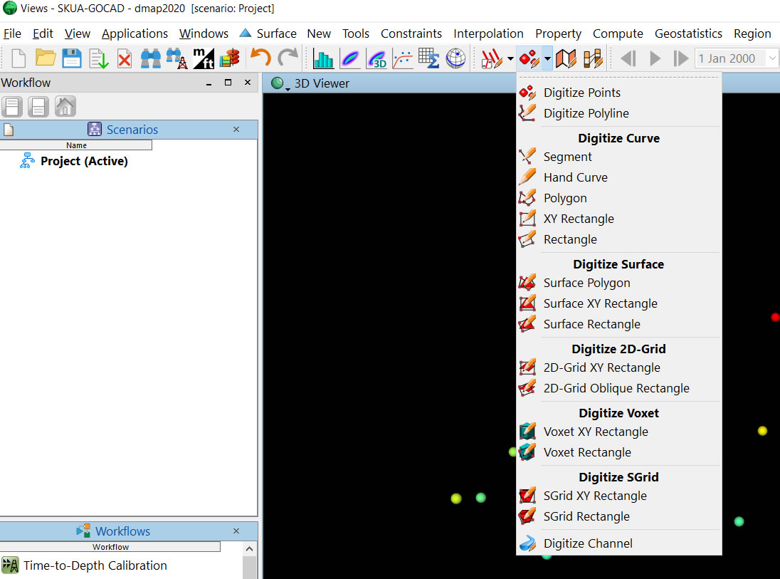
Note, there are plenty of ways to do this, and different approaches are more useful depending on the data you have. Furthermore, the documentation in Gocad for making 3-D objects is not particularly straightforward or complete. For example, they have many "choices" for digitizing faults (see image below). It turns out these are just really different ways of creating points, lines, or surfaces and whether or not they are constrained to an existing surface, not really faults per se. I encourage you to play with each of these and see what they do. Note also that when some of these are created they become " unassgined objects" and so you have to turn on the unassgned display element in the explorer bar on the left side. In fact, the next pulldown to the right will actually make objects that "belong" to the horizon of interest.
It is possible to draw a "Fault Polygon" and then cut a hole in the surface with Tools-> Edit-> Cut-> By Curves. While this is similar to what is done in conventional mapping programs when making fault polygons, I don't like this because every horizon is treated differently and there isn't really a fault suface itself, just fault gaps in the horizon surfaces. One of the main points of Gocad is to make a 3-D model that has horizons abutting faults with everything "water tight." That is, that the model is fully connected and can be used for other purposes such as fluid flow modeling or fault-plane analysis, to name a couple. So we want to make a fault surface and then cut the horizons with the fault.
One way to make a fault surface is to directly make a "Fault Surface" with the above menu and then sculpt the surface with Tools-> Node-> Move by Dragging. I find this approach often difficult to accomplish. Sculpting in 3-D is not trivial! I reserve this approach for very little moves, or tweaks.
So I like to make ribs (contours if you will) of the fault and connecting them as a surface, or making fault traces in the vertical plane and then connecting these to make a surface. The advantage to the former, is you can draw the ribs right on the horizon and so define the break in the surface right at control (know points) you have. The advantage to the latter is theoretically you can define the dip(s) of the fault exactly. You can also connect fault cuts (reported faults in wells) if you have them.
Shown here are steps to make fault traces, combine them into a fault and then cut the horizon with the fault. You can abstract the approach for ribs.
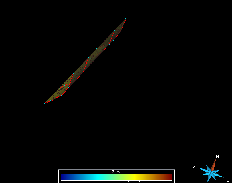
1. First you have to make a vertical plane to draw fault trace on. View South (right icon that shows a red plane) and then draw XY Rectangle.
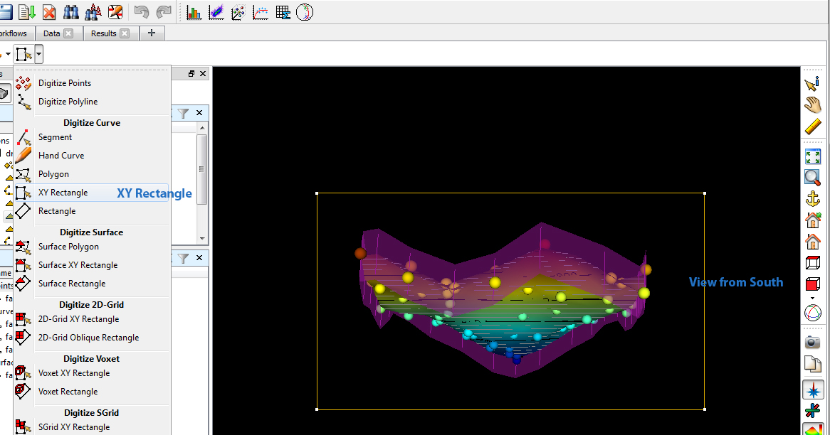
2. Make this rectangle a surface with New-> From Closed Curve.
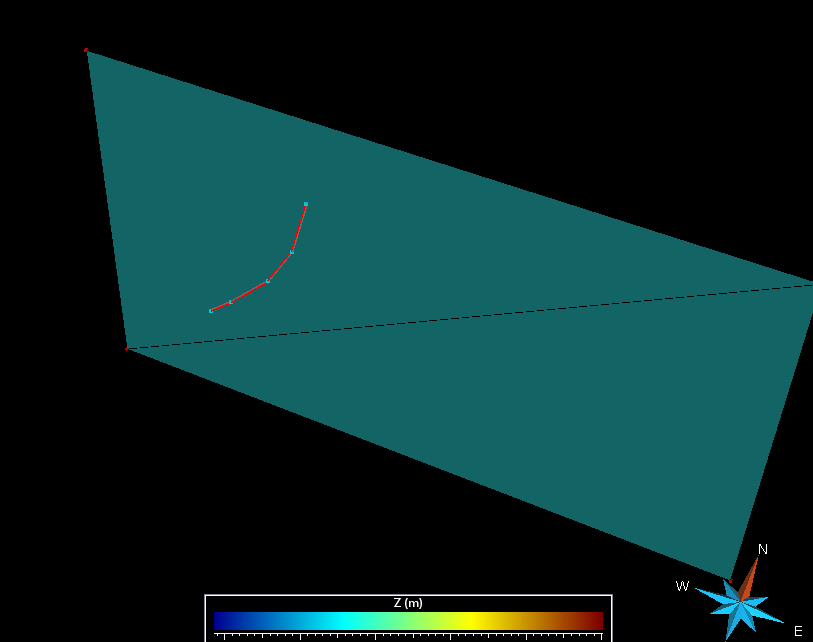
3. Draw a new curve on the surface that is the fault trace with Digiztize Polyline on the same pulldown.
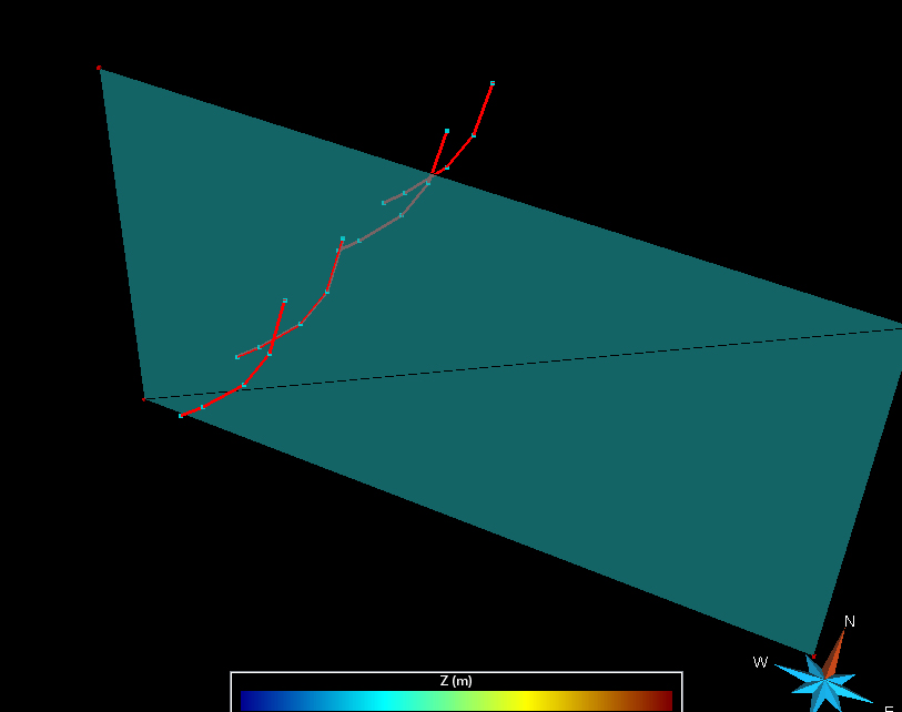
4. Make a couple of copies of the trace by right clicking in the explorer window. Then translate with the Curve Menu at the top Tools-> Part-> Move with Vector. From this window use the arrow to pick the strike direction and then drag it a little. This will populate the Direction Vector. It is cleanest if afer you do this, you make Z Dir Vec = 0 so that you are only moving in the X and Y directions (otherwise you will get a surface that has irregularities).
5. Now connect the fault traces together as a new surface with Surface Menu Tools-> New-> From Several Curves.
NOTE HOLD THE CONTROL KEY DOWN TO SELECT ALL FAULT TRACES.
Also hide the XY plane.
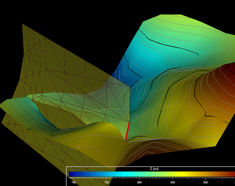
6. Cut the original surface with the fault by choosing from Surface Menu Cut-> By Surfaces.
Check Build Constraints as well as Beautify Intersection (almost always what you want).
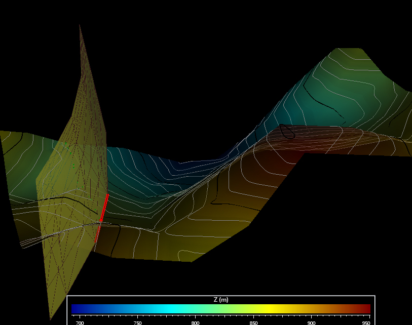
7. Make sure the constraints on the surface are still present and run the interpolation and if done right you should have a faulted fitted surface.
Note, it is water tight agains the fault.
C. Connors